
As a Hardware Design Engineer on the ADS-B team at FlightAware, Ziquan Wang is responsible for maintaining and designing the current and future SDR hardware of FlightAware’s ADS-B receiver network. In addition, he is currently pursuing an MBA at Rice University.
As a Senior Software Engineer on the ADS-B team at FlightAware, Eric Tran contributes to the software development and growth of FlightAware’s terrestrial ADS-B receiver network.
Summary
In this blog post, Ziquan and Eric discuss the hardware and software architecture of the software defined radio that powers our ADS-B receivers.
Hardware Architecture
Radio Frequency (RF) signals broadcasted from nearby aircraft get filtered and processed by several components within the Software Defined Radio (SDR). We are going to go through the hardware architecture of the SDR by following how the signal flows through the hardware device.
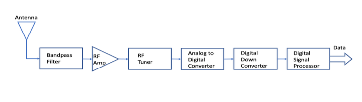
The entry point of the RF signals is the antenna. FlightAware has two official antennas that we provide with our ADS-B receivers. The first is an outdoor-capable antenna that has high gain and is tuned to maximize the reception of signals at 1090MHz. The second antenna is what we call a small coil antenna, which is what we ship with our new PiAware ADS-B Kit. It has less gain and is intended to be used indoors.
The signal passes through the RF filter, which is responsible for filtering out unwanted RF energy, also known as “noise.” Even the highly tuned outdoor antenna can still pick up a good amount of noise, especially if the ground station is in a big city, where the RF energy from cellular towers and local TV stations can easily saturate the LNA if the signals are not filtered first. We supply an external filter that has low insertion loss and the best out band rejection among all our product offerings.
A Low-Noise Amplifier (LNA) is an amplifier that is designed to amplify the signal without adding significant noise to the signal chain. A good LNA can increase the coverage and message rate of the SDR. This was proven when we added a on-board LNA to the standard RTL-SDR to make FlightAware ProStick. Later we released the ProStick Plus that had an on-board filter after the LNA. This was designed with the intention of minimizing the impact of signal loss from the filter. This product is suitable for people who live in areas with low RF noise environment (e.g., rural areas).
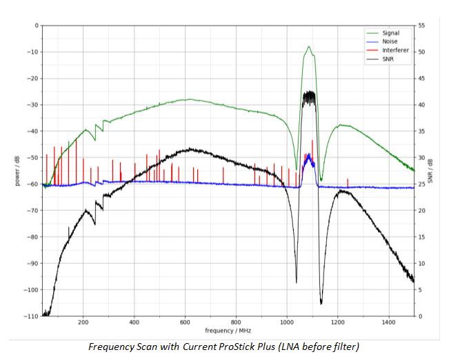
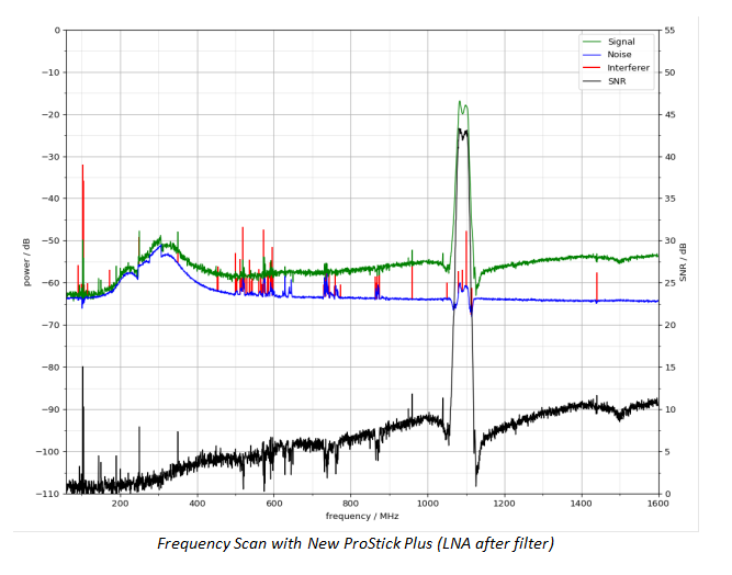
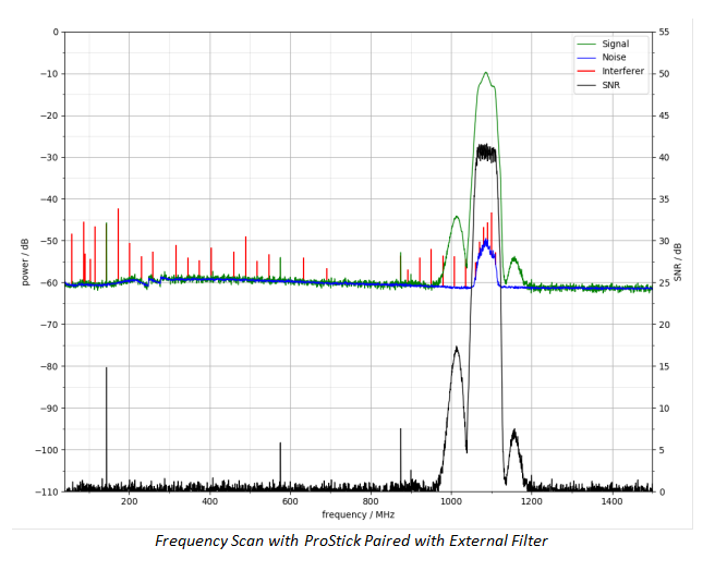
We are working on an alternative ProStick Plus model that has a high-performance filter before the LNA for people who want to minimize cost and place their ground station in an RF noisy environment. Below are some diagrams of the results we found during the prototyping of this new model. We developed a test setup to scan the frequency response of our products and prototypes. It measures the strength of signal, noise floor, and interferer to calculate the signal-to-noise ratio (SNR).
The interferer below in red is identified to be the spikes picked either externally or internally. It can be the emission from the clock lines or the imperfection of RF generator.
The most important factor among these graphs is the signal-to-noise ratio (the black line). When the test subject receives the sweeping signal from low to high frequency at equal power, the higher SNR means the better reception at that frequency. For ProStick Plus, there are some rejections outside its passing band. For the new alternative ProStick Plus model, it has significantly better rejection outside passing band. For the Pro-Stick paired with External Filter case, the rejections below 900MHz and above 1200MHz are almost perfect.
The signal then passes through the signal mixer. FlightAware Pro-Sticks use the R820T2 Integrated Circuit (IC). The R820T2 will soon be replaced by the R860, which is almost identical to R820T2. This IC has a frequency mixer and variable frequency generator to convert any frequency signal in the reception band to a standard intermediate frequency signal. Wikipedia has very good articles and pictures that detail the principle of operation here.
We are currently exploring other receiver ICs that can bring better analog RF performance and provide two receiver channels to our ground station offering.
The intermediate frequency is then sampled by an Analog-to-Digital Converter (ADC). In our current RTL-SDR based design, we use an 8-bit ADC in the RTL2832U IC, which samples at 28.8MHz. After being resampled, the data is delivered to the Raspberry Pi through its internal USB2.0 controller. We are exploring improvements to the ADC to see if we can improve signal reception of the ground station. The preliminary data seems to be promising. When the RF input is terminated and all gain settings are dialed down to 0, the raw ADC data was collected from the Pro-Stick and prototyped with a 12-bit ADC. Results show the voltage variation range of 12-bit ADC is within one bit of 8-bit ADC. One incrementation of 12-bit ADC is 0.49mV and one incrementation of 8-bit ADC is 7.8mV.
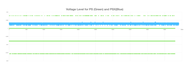
This suggests that the 12-bit ADC can have much less noise floor and possibly better resolution than the 8-bit ADC. Additionally, a higher, variable sampling rate will give our hosts more freedom to explore what combination of bit-width and sampling rate is the best for their application.
Through theoretical calculation, the data rate from USB2.0 is not enough to sustain the raw ADC data rate at higher sampling frequency. We are going to introduce a USB controller capable of USB3.0 protocol. We are trying to release new in-house designed hardware to bring better performance than RTL-SDR-based hardware. The global supply chain shortage has been slowing down this process.
Once the analog signal has been converted by the ADC, it’s then sent to our demodulation software.
Software Architecture
In our last ADS-B blog post, we introduced dump1090-fa, FlightAware’s fork of the original dump1090 software. It is used to interface with RTL-SDRs to demodulate and decode ADS-B, Mode-S, and Mode A/C signals. We’ll dive a little deeper to understand how the demodulation software works. It may be beneficial to read about Mode-S and ADS-B to understand the data formats and what information we can extract from them. The 1090 Megahertz Riddle is a good primer.
Data acquisition
dump1090-fa spawns a background thread that is responsible for data acquisition. This thread asynchronously reads samples from the SDR and pushes that data into a shared FIFO queue. The main thread consumes and processes the data from this queue. Because both threads are simultaneously reading and writing to the same memory buffer, it is protected with a mutex to avoid any potential race conditions.
Data processing
There are two steps in processing the sample buffers: demodulation and decoding.
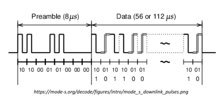
Demodulation extracts the original information from a carrier wave into a stream of bytes. The main thread of dump1090-fa consumes the data from the shared FIFO queue and sends the sample buffers to the demodulator. The demodulator scans through the input buffer for an 8 µs preamble for a series of pulses with specific timings known as the Mode-S preamble (see diagram below). If a preamble is found, it demodulates the remaining data block and conducts some extra validation to determine if this is a valid Mode-S message.
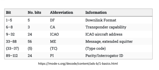
At this point, the Mode-S message has been demodulated into a stream of bytes to be decoded. The first 5 bits of the data block are known as the format code, which we can use to determine how to process the rest of the message. We are particularly interested in 112-bit Extended Squitter messages, which is used by Automatic Dependent Surveillance-Broadcast (ADS-B) systems to transmit position, velocity, identification, etc. information. These messages have a Downlink format code of 17 (DF17). The full breakdown of ADS-B message bits is shown in the table below.
Here is an example of a raw ADS-B message and the aircraft information decoded from it.
RAW message:
8da21c4c5815a206490d97d23613 Decoded message:
CRC: 000000
Score: 27 (DF17_KNOWN)
Time: 623188.92us
DF:17 AA:A21C4C CA:5 ME:5815A206490D97
Extended Squitter Airborne position (barometric altitude) (11) (reliable)
  ICAO Address:  A21C4C (Mode S / ADS-B)
  Air/Ground:    airborne
  Baro altitude: 3250 ft
  CPR type:      Airborne
  CPR odd flag:  even
  CPR latitude:  33.03680 (66340)
  CPR longitude: -97.00889 (69015)
  CPR decoding:  global
  NIC:           8
  Rc:            0.186 km / 0.1 NM
  NIC-B:         0
Data streaming
Dump1090-fa processes the aircraft data into a variety of different formats. It creates several listener ports that clients can connect to for sending and receiving the data. To take a closer look at some of the available output data, we will be using the network utility, Netcat, to open a TCP connection on each port. If you have a PiAware running dump1090-fa, you can follow along on the command line to view the output on your local receiver.
Port 30002 outputs the raw aircraft data in hexadecimal format. We can see this data by entering the following command:
pi@piaware:~ $ nc localhost 30002
*200003BDC92229;
*02818316F69033;
*02618218DCB383;
*0281839CF04118;
*02E19A1F53AFC4;
*02059422ED6FFD;
*5DA6976129386D;
*02A1853C97BFE4;
*8DA2C90DE11A0F00000000F90A57;
Port 30003 outputs aircraft data in BaseStation format.
pi@piaware:~ $ nc localhost 30003
MSG,7,1,1,ABFE12,1,2022/04/02,01:56:36.924,2022/04/02,01:56:36.977,,2250,,,,,,,,,,
MSG,7,1,1,AA4A90,1,2022/04/02,01:56:36.929,2022/04/02,01:56:36.979,,2175,,,,,,,,,,
MSG,6,1,1,AA295D,1,2022/04/02,01:56:36.930,2022/04/02,01:56:36.979,,,,,,,,1511,0,0,0,
MSG,3,1,1,AD7828,1,2022/04/02,01:56:36.941,2022/04/02,01:56:36.981,,1800,,,32.91406,-96.91354,,,0,,0,0
MSG,7,1,1,ABFE12,1,2022/04/02,01:56:36.943,2022/04/02,01:56:36.981,,2250,,,,,,,,,,
MSG,5,1,1,A22B28,1,2022/04/02,01:56:36.945,2022/04/02,01:56:36.982,,10025,,,,,,,0,,0,
MSG,3,1,1,AB674B,1,2022/04/02,01:56:36.958,2022/04/02,01:56:36.984,,21375,,,32.81689,-96.14262,,,0,,0,0
MSG,7,1,1,ACAB11,1,2022/04/02,01:56:36.964,2022/04/02,01:56:36.985,,15550,,,,,,,,,,
MSG,7,1,1,AA15CC,1,2022/04/02,01:56:36.966,2022/04/02,01:56:36.985,,1650,,,,,,,,,,
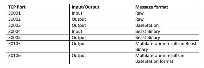
MSG,4,1,1,AB674B,1,2022/04/02,01:56:36.968,2022/04/02,01:56:36.986,,,475,83,,,640,,,,,0 Depending on what type of format a client application needs, they can make TCP connections to the appropriate ports to stream the data. Notably, our piaware client connects to Port 30005 for aircraft data in beast binary format to process and upload to FlightAware. The table below shows all the available ports and their respective data formats.
Aircraft Tracking
Dump1090-fa also generates several JSON files with information about the receiver, current aircraft detected, and general decoder statistics. These files are consumed by the SkyAware map interface to display the aircraft data the receiver is receiving in real time. These files get written to the temporary runtime directory /var/run/dump1090-fa/. Some sample output of aircraft.json below.
{
  "now": 1649040909.2,
  "messages": 30451161,
  "aircraft": [
    {
      "hex": "aa6a98",
      "alt_baro": 8950,
      "alt_geom": 9275,
      "gs": 288.1,
      "track": 64.9,
      "baro_rate": -1344,
      "lat": 32.46446,
      "lon": -97.035006,
      "nic": 8,
      "rc": 186,
      "seen_pos": 2.1,
      "version": 0,
      "nac_p": 8,
      "nac_v": 1,
      "sil": 2,
      "sil_type": "unknown",
      "mlat": [],
      "tisb": [],
      "messages": 19,
      "seen": 1.9,
      "rssi": -21.4
    },
    {
      "hex": "aaec9c",
      "flight": "AAL2190",
      "alt_baro": 3200,
      "alt_geom": 3100,
      "gs": 200,
      "track": 179.4,
      "baro_rate": 1280,
      "squawk": "2355",
      "emergency": "none",
      "category": "A3",
      "nav_qnh": 1008.8,
      "nav_altitude_mcp": 16992,
      "lat": 32.837436,
      "lon": -97.030577,
      "nic": 8,
      "rc": 186,
      "seen_pos": 0,
      "version": 2,
      "nic_baro": 1,
      "nac_p": 9,
      "nac_v": 1,
      "sil": 3,
      "sil_type": "perhour",
      "gva": 2,
      "sda": 2,
      "mlat": [],
      "tisb": [],
      "messages": 407,
      "seen": 0,
      "rssi": -16.7
    },
    {
      "hex": "a8aa87",
      "flight": "AAL1966",
      "alt_baro": 12025,
      "alt_geom": 12375,
      "gs": 300.6,
      "track": 44.1,
      "baro_rate": -1280,
      "squawk": "7404",
      "emergency": "none",
      "category": "A3",
      "nav_qnh": 1008,
      "nav_altitude_mcp": 4000,
      "lat": 32.74098,
      "lon": -97.214318,
      "nic": 8,
      "rc": 186,
      "seen_pos": 0.4,
      "version": 2,
      "nic_baro": 1,
      "nac_p": 9,
      "nac_v": 1,
      "sil": 3,
      "sil_type": "perhour",
      "gva": 2,
      "sda": 2,
      "mlat": [],
      "tisb": [],
      "messages": 436,
      "seen": 0.2,
      "rssi": -17.2
    }
  ]
}
More details about these JSON data can be found on Github.
Conclusion
We hope this post gave you some insight into the software defined radio that powers our ADS-B receivers. We have designed the FlightAware Pro-Stick and Pro-Stick Plus to be one of the best SDRs on the market and are continuing to iterate and innovate on the designs for our next generation of FlightAware hardware products.